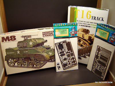
Step 1 of building Tamiya's M8 Howitzer Motor Carrier is the chapter slightly misnamed "Construction of Wheels". The reason I pedantically say it is misnamed is because firstly the (physical) wheels themselves do not require assembly, and secondly because this chapter actually deals with the assembly of the suspension and the idler wheel units (I actually do not know what the section attached to the idler gear is called, hence: "unit").
As mentioned above, this step covers building the vehicles four suspension units, each with two road wheels attached, and the two idler wheel units. During this stage I also got my first taste of PE and scratch-building, albeit miniscule, for the kit.
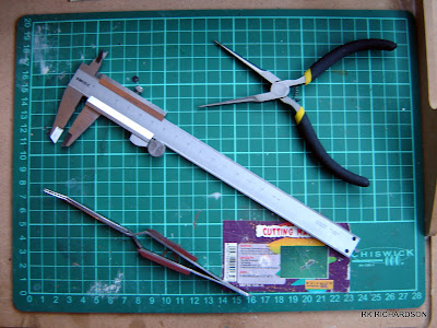
The first thing I do when starting a new chapter, or stage if you prefer, of a modelling project is re-read the instructions relevant to the chapter. Not only the kit instructions though, but also the instructions of any aftermarket (AM) products I will be using to enhance the kit. I normally read ahead through the instructions, ascertaining if there is anything ahead in the build which would make more sense to include at this stage (be it logical sense or from a sub-assembly/painting point of view).

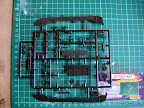
Above are the Tamiya kit instructions relevant to this chapter.
Step 1.1: Suspension
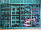
I decided to start this chapter by assembling the suspension units. As I always do when required to assemble multiple (and identical) units, I identified the six parts required for assembling one of the units and removed them from Sprue B, placing them in a plastic container labelled "Suspension". By placing them in the labelled container I ensure that I can easily find all the parts relevant to the section or sub-assembly, as well as reduce the risk losing them and them attracting dirt and dust. The reason I only remove the parts for one sub-assembly is so that I can do a "dry run" on the assembly, working out any pit-falls that may occur during the assembly, and checking for any seams and casting flaws (which would most likely be persistent on the other, identical parts as well).
Clean up was minimal, and quite normal for virtually any plastic model kit: there were the usual fine casting seam lines. The casting seam lines on the wheels were sanded down using a medium grit sandpaper. The reason I used the medium grit sandpaper was because I wanted to leave a slightly rougher looking finish on the solid rubber road tyre. The rest of the parts were sanded down with a fine grit sandpaper, with heavier seams being reduced first using a hobby knife. While cleaning up the parts, I also took the opportunity to remove the two top bolts on part B17, as instructed by the kit instructions.
Before applying glue to parts it is always a good idea to dry-fit (or test-fit) the parts together to check how, and in which order, they are going to go together when doing the real fit. The kit instructions call for part B10 to be fitted to the rest of the assembly last. I found it was easier to fit the wheels (B10) to B17, and then fit B10. B16 could slide into place over the wheels and into the slot on B17, and seated itself with its arms sitting on the small brackets provided on parts B17 and B10. B7 slotted into place over B16. Placing the completed suspension unit against the lower hull, I also checked the fit against the hull. And thus the suspension sub-assembly was completed, albeit only dry-fitted together.

Having completed the first suspension unit, I clipped all the parts for the remaining units off the sprue and stored them my plastic container. As at this stage the parts and units were all identical (at this point they are neither left or right, front or back) it did not matter that they were all mixed in the tub. Clean-up was as before, as was the dry-fitting of each unit.
Another one of the useful purposes of performing a dry-fit of the sub-assembly is determining to what extent the sub-assembly should be completed, and what needs to be left off for the later painting stage. I decided that painting the road wheels and the inside of the suspension units would be rather difficult it the sub-assembly were completed in its entirety. And thus I determined that it would be best not to glue the wheels and part B10 into place when doing the final assembly.
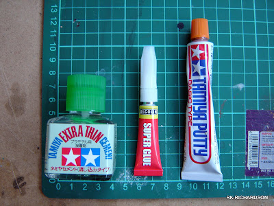
The final assembly of the suspension was approached in the same manner as the dry-fit. The exception being that the mating surfaces of parts were treated to a dab of Tamiya Extra Thin Cement - the exceptions being those parts I mentioned above which would not be fixed into place just yet.
You will recall that I mentioned reading ahead in the opening paragraphs. When reading ahead, I noted that in Chapter 4 Fixing of Wheels part B2, a D-shaped part which I think is some sort of track return guide or roller, is fitted on top of the suspension unit. I decided it make sense to attach these parts to the suspension units prior to painting, and thus decided to attach them during this chapter. Since the fitting of these parts would effectively define the suspension units as left or right, front or rear, I temporarily placed the suspension units into position and glued the part (B2) into place. I also noted that there was a small gap left on top of the suspension unit. Since I would be leaving the side-skirts off later, this would be visible so filling was required (I do not generally spend too much time cleaning and filling parts that will not be seen). The filling was done with a smear of Tamiya Putty, smoothed when wet with an old hobby knife blade, and later sanded smoother still.
A quick note on the M8 HMC's road wheels: The Tamiya kit is supplied with the open spoke road wheels, however it appears M8 HMCs used these open spoke wheels, the cast wheel, the closed (or welded) spoke wheel, or any combination of these. I have not seen any pictures of the closed spoke wheel used on the M8 HMC, however I am led to believe by those more knowledgeable than me that similar vehicles were using these toward the end of the war so it is fair to assume this was applied to the M8 HMC as well. There are resin replacement kits of the cast wheel available, but as I did not want to spend much more on the kit, I decided not to purchase as set. I believe that as there are a few photos of the open spoke wheel used, I am satisfied that this falls within my reasonably accurate satisfaction level.
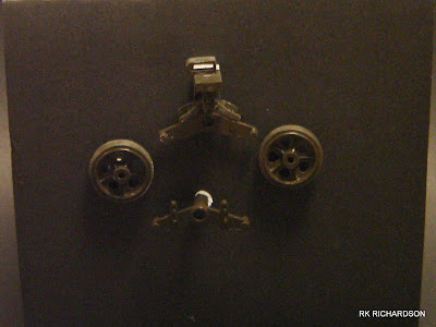
The four sub-assemblies (main sub-assembly, two wheels, and part B10) making up each suspension unit.

The four completed suspension units, the four subassemblies dry-fitted together.
Step 1.2: Idler Wheels
Part two of Step 1 Construction of Wheels concerns the assembly of the two idler wheel assemblies. This was also the first stage during this build where I used PE and was required to do some scratch-building (sure it was only cutting plastic from a sheet, but scratch-building nonetheless).
Each idler wheel assembly consisted of three kit parts. With the exception of the idler wheels themselves, the left and right arms were easily differentiated from the other. Once removed from the sprue and cleaned each assembly was dry-fitted. Once again due to wanting to paint the wheels separately I left the units broken down.
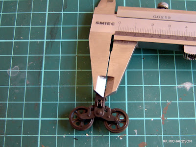
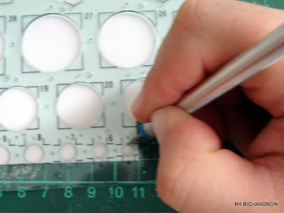
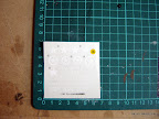
This brings us to my first attempt at the kit's PE. The Eduard M8 HMC Exterior PE Kit requires the fitment of a small circular plate (presumably it is part of the idler wheel's suspension arm, perhaps a filler cap for suspension fluid?) to parts B3 and B4, with a 1mm spacer between the kit part and the PE.
By my reckoning there were two ways I could approach making the spacer. Option one was to cut the circle, then glue three parts together. Option two was to glue the PE (using CA glue) to the plastic card and then cut around the PE, creating the circle, and fix this to the kit part. I chose the latter, although in retrospect the former would have been the correct way to approach this task. In actual fact, once the PE was glued to the plastic card I did not cut a circle, but rather a square, and then nibbled away at it until it was cropped in under the PE. A bit rough, but it worked nonetheless. The part, once resembling a circle, was glued to the kit part. Once the glue had dried, the shape slightly further refined using sandpaper. And so my first PE and scratch-building experiences with this kit were complete.
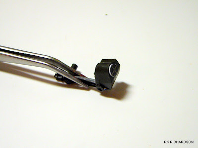
Part B4 with spacer and PE part fixed.
The Eduard M8 HMC Exterior PE Kit provides wedge shaped pieces of PE which should be fitted between the spokes (both sides of the wheel) of the idler gears and effectively make it a solid idler gear. I have noted in photographs that quite a few M8 HMCs operated using the spoked idler wheel. For this reason as well as my decision to use the open road wheels, I decided not to use the PE parts, and to leave the idler wheels as the open version.

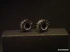
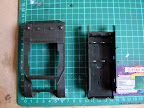
The components/sub-assemblies making up the left idler wheel unit.
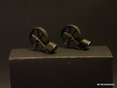
The two idler wheel units, dry-fitted together.
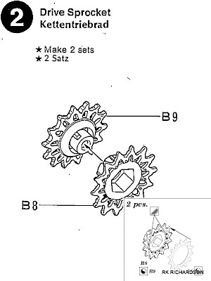
In the next chapter we will assemble the drive sprockets.