Tuesday, 24 February 2009

M8 HMC: Step 4 Fixing of Wheels

"Step 4 Fixing of Wheels" is the fourth and final chapter in the assembly of the lower hull of Tamiya's M8 Howitzer Motor Carriage. In truth "Fixing of Wheels" is somewhat of a misnomer as the chapter deals with more than merely attaching the bogey's (road wheel suspension) to the lower hull, but as seen in the below instructions also includes attaching the drive sprockets, idler wheels, engine access doors and towing pintle.

This chapter also sees me embarking upon my first serious adventures in photo-etch (PE); at this stage of the build I will also be bending and assembling the two exhaust deflector boxes as supplied in the Eduard M8 HMC Exterior PE set.

Above are the Tamiya instructions for Step 4.

As can be seen from the above kit supplied instructions, most of the assembly taking place during this stage involves fitting the bogeys, idler wheels and drive sprockets as assembled in Step 1 Construction of Wheels and Step 2 Drive Sprocket respectively. However, as stated in the former post, as I will be painting these items separately to the vehicle, I will not be attaching them to the lower hull during this stage. In addition, recall that I attached the track guides (the four B2 parts) to the tops of the bogeys in Step 1 Construction of Wheels.

And so, with these sub-assemblies being excluded from this stage, all that remained for assembly were the small track roller wheels, the engine access doors, the towing pintle, and two towing eyelets.

As I am building a early-mid version of the M8 HMC, I elected to leave the towing pintle (A25) off, and so filled its locating indentation with Tamiya filler putty and sanded it smooth. The small track roller wheels (the six B12 parts) were glued to the locating lugs. As dry-fitting revealed them to fit a tad loosely, caution was exercised when gluing them into place and ensuring that they were parallel to the lower hull. The next kit part to be fitted was the engine bay access doors and overhang, represented in one piece (A20). I noted that the gaps between the doors did not extend all the way between door hinges, and so used a scribing tool complete these lines. A20 was then glued into place on the lower hull.

Above is the lower hull tub showing the small track roller wheels fitted.

One of the more glaring mistakes on the lower hull of Tamiya's M8 HMC is the exclusion of the two exhaust deflector boxes. Fortunately Eduard comes to the rescue, and provides both the lower box and two different versions of the upper box. And thus I steeled my nerves to tackle my first serious bit of PE work.

Above L-R: A neat trick for removing PE from the fret; and bending large pieces of PE. See text for details.

When working with PE a far amount of caution should be practiced when both removing it from the fret and handling it. Unlike plastic, PE lost to the dreaded "carpet monster" can leave a rather nasty cut when found by a bare foot. Similarly, when handling PE parts by the edges, remember: it is fine metal and it can cut! Fortunately none of these warning are due to self-experience.

A tip I picked up on Armorama with regards to removing PE from the fret is to place a piece of masking tape on your cutting surface (for PE I use a glass surface as it does not yield to the knife resulting in a neater cut). Place the part to be removed on the masking tape and then cut down using a chisel blade. This prevents the part from shooting off and being lost on the floor or carpet ("carpet monster"). The above left picture demonstrates this.

I do not (currently) have any fancy PE bending tools, so have to make do with the basics: steel ruler; broad chisel blade; and flat long nosed pliers (i.e. no teeth). To bend a broad piece of PE, such as the deflector boxes, all I do is firmly hold down the PE under the steel ruler with the fold lines (those slight lines you see on PE) lined up with the ruler, and then gently bend, or prise, the PE up using the broad chisel blade. The above right picture demonstrates this. To bend smaller parts all I do is grip the part securely using my flat long nosed pliers, again with the “bend line” aligned to the edge of the pliers, and gently bend it (the part) again using the chisel blade.

Above are the Eduard M8 HMC Exterior exhaust deflector box instructions.

The first two PE parts to be fitted were the brackets noted in the topmost cell of the above image. The two PE parts, both numbered 31, were bent at a right angle into a L-shape, and then glued (using CA glue) into place slightly above the bottommost door hinges. You may note the other items in this cell – this have been excluded until I begin work on the upper hull.

Next on the line up was the lower deflector box. Being a straight forward rectangular box (PE part 11), this was definitely the easier of the two and the better option to start more complex PE bending on. I started by folding one of the longer sides up to a right angle to what would be the back of the box, in fact if you refer to the steel ruler/PE bending image above you will see this being done. Once that had been completed, I held down the opposite side using the steel ruler and folded the back of the box to another right angle. I now had a U-shaped box. The two shorter sides were simply folded up using flat pliers, and then the edges glued using CA glue.

Having completed the basic box, I now had to insert the inner. The inner consists of four parts, a long flat piece (part 7) destined to become a U-shape and three small cross-pieces (part 33), each with a slot to meet with a corresponding slot in 7. Part 7 was shaped by first bending one side to a right angle as described above and then, due to the thin face of the backing, held down using my chisel blade and bending the part gently using pliers. Perhaps not the prettiest method, but it worked. Parts 33 were glued to part 7 and the unit slid into the box (11) and glued into place. At this point I elected not to glue the mesh grill into place as I felt that during priming and pre-shading the grill would most certainly clot. This would also present the opportunity so spray the inside of the box black before it was closed by the grill. I feel I should add that in honestly I did have a difficult time getting the box correctly placed, and was forced to remove and refit it several times. As result the box does appear slightly battered - but in my opinion given its location on the vehicle it would most likely be easily battered anyway.

Eduard provide two options for the upper deflector box, the early one piece unit and the later two-piece which appears to wrap around the towing pintle. As the towing pintle was only (factory) fitted to the last 174 vehicles (of some 1,778 odd built) and mine meant to be an early-mid model, I decided to forgo the pintle and thus the two-piece deflector. The earlier one piece deflector folds into a L-shaped box, and certainly not the easiest shape for a PE newcomer to fold. The approach to folding it requires plenty of forethought.

The lower deflector is a L-shaped box which requires the modeller to create a Z-bend - being (if you picture an L-shaped box) the top of the "foot" of the L, the front of the vertical front, and the closed-off top of the vertical. As there is also an interior to be inserted, one does not want to close the box entirely too early. So with this in mind, using the folding techniques described before and after thoroughly studying PE part 32 I set about folding the long edges. I folded all the edges to about 45 degrees first, and then with the box taking shape started gently folding these longer sides, with the exception being the front of the box (the top of the "foot" of the L and the front of the vertical front), until the sides were all at the desired angles. I then inserted the interior, consisting of the three part 23's and the long part 6, dry-fitted together into the box, and then closed the box. The reason I inserted the dry-fitted interior is because I wanted to line it up in the box before gluing it together - which is what I did once the box had been closed. The box was then glued to the plastic lower hull in the indicated position.

For the same reasons as the lower deflector box, I chose not to fit the mesh grill at this point in time. I also decided not to fit parts 32 and 45 at this time. It appears to me that these parts need to meet the upper hull, and thus I will attach them when fitting the upper to the lower hulls.

The final parts to be fitted during this stage were the pair of towing attachment points (A9) and U-shaped hooks (A6). These were glued into place and the slightly raised edges sanded smooth.

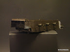
Above L-R: A view of the rear showing the fitted deflectors; and a right-rear view showing the completed stage.

The next chapter, Step 5 Turret 1, is one of the longer chapters featuring the construction of the left and right sides of the turret - with many PE additions.

Saturday, 21 February 2009

Joachim Peiper and LAH NCO in the Ardennes

Manufacturer: Alpine Miniatures
Item Code: 35075, 35076, 35077
Medium: Resin
Sculptor: Taesung Harmms
Box Artist: Calvin Tan
Review Publication Date: February 21st 2009
WWII German Panzer, or even Waffen-SS, officers are not a unique subject, but what sets these figures apart from the rest is the manner in which Taesung has combined the various elements of Panzer and winter gear and picked up on the very many nuances present in WSS uniformology. Add in the masterful sculpting of Taesung Harmms and the high quality casting of Alpine Miniatures and you have a really nice set of figures with a lot of painting potential.
Click here for my review on Historicus Forma

Friday, 6 February 2009

M8 HMC: Step 3 Fixing of Drive Shaft

"Step 3 Fixing of Drive Shaft" is one of the shorter steps in assembling Tamiya kit 35110 M8 Howitzer Motor Carriage. It is also one of the easier - provided you simply follow the instructions and not deviate slightly as I did. Be that as it may, even with my minor changes this remains an easy and short chapter.

Above are the relevant Tamiya kit instructions.

As indicated above this step requires the attachment of two pairs of parts, namely the two drive shafts (A26 and A27) and what I assume to be two towing attachment points (both numbered A29), to the lower hull.

There is really not much to say about the actual attachment of these parts to the lower hull. There was the usual molding seams which needed to be cleaned, and then the parts were glued into place using Tamiya liquid glue. One thing I have noticed is that if the towing points are attached correctly per the kit, they do not angle down as with the real vehicle. I have chosen not to correct this minor blemish. The gaps around the drive shafts and the lower hull were filled with Tamiya putty - as is evidenced by my messy handiwork in below photos.

Above left shows the front of the lower hull and the tow hooks which should angle down. Above right is the drive shaft in place before filler putty is applied.

When paging through the Tankograd M8 HMC book, I noticed that the transmission (basically the front section of the lower hull which the drive shafts are attached to) features four bolt heads and what I think is a grease hole on each side of the front face. However the Tamiya hull does not represent this detail, replacing it with an ignominious casting seam.

Correcting this little detail was simple. "Guesstimating" when the grease holes should be, I gently drilled the holes using a 0.5mm drill bit and my pin-vice. I then glued two pieces of the 0.5mm styrene hex rod I had cut previously above the hole, and two below on each side of the transmission. I must admit to being skeptical that I got this 100% accurate (or even vaguely), but it looks the part so I am satisfied.

Back in the '80's when this kit was originally produced, it was released as a (electric) motorised model. The tell-tale signs can still be seen by the holes in the lower hull and some sort of struts for batteries. Given that the holes are on the underside of the hull I suppose one could ignore them, however I decided to fill them. I did this gluing a small piece of plastic card inside the hull, and then filling the holes with Tamiya putty.

Above left shows the plastic card over the holes. Above right shows the holes filled with putty prior to being sanded smooth.

Above shows the completed Step 3 Fixing of Drive Shaft with transmission bolts fitted.

The next chapter, Step 4 Fixing of Wheels, is a larger one wherein we will also tackle folding photo-etch and creating PE boxes.

Saturday, 31 January 2009

M8 HMC: Step 2 Drive Sprocket

Step 2 in building Tamiya’s M8 Howitzer Motor Carrier is titled “Drive Sprocket”, and deals with exactly that: the assembly of the track drive sprockets. In theory this is an easy step, with the modeller required to assemble two drive sprockets, each consisting of two parts. Unfortunately Tamiya got the track drive sprockets a bit wrong, so although this chapter is still fairly simple, it is not as simple as gluing two parts together.

As I mentioned above, Tamiya got the look of the track drive sprocket wrong: they provide an open sprocket, when in actual fact the M8 HMC was fitted with a solid drive sprocket. Fortunately the Eduard exterior PE set supplies four solid sprockets which can be fitted over both the inner and outer sprockets to make them look the part.

Above are the Tamiya kit instructions relevant to this chapter. The inset shows the Eduard instructions.

As you see from the above instructions, each track drive sprocket consists of only two parts, the inner sprocket (B9) and the outer sprocket (B8). After removing the parts from the sprue and cleaning up any blemishes, my first task was to remove the moulded bolt heads from the outer sprocket. I did this simply using a chisel blade fitted to my hobby knife, but I guess you could also use the grinding head of a rotary tool if you really fancy. Now the kit parts were ready to receive the PE sprockets.

A note to newcomers to photo-etch: photo-etch really can be quite sharp, so you really should practice caution both when removing it from the fret (the frame the PE is attached to) and when handling it.

Aligning the PE parts with the kit parts was simple enough – when dry-fitting it, that is. Why do I say that? Well, if you think about it, when aligning the PE part with the kit part you have to align each point of the PE part with the underlying plastic part – so you have fourteen points to align! Although fairly simple, it can be time consuming. Now try to do it with CA glue applied!

So here is how I handled this problem – and I must confess I only realised this method on a second go at aligning a set of parts. What I did was broke the task down: I only applied CA glue (note that I do not apply it directly from the tube, I put some on a piece of plastic card and then apply with a sharpened match stick or toothpick) to half the plastic part, and then quickly placed and aligned the PE part. Once the glue had set, I gently prised the unglued section of PE up, as seen in the below photo, applied more glue, and then pushed it back into position and clamped the whole part.

Above left you see one of the outer sprockets completed, while other has half the PE bent up for ease of gluing. Above right you see one of the sprockets being clamped.

The whole purpose of the PE parts is to transform the open track drive sprocket into a closed on. However, placing the part does not complete the transformation. When looking at the sprocket, one could see the gaps: one could see the gap in the centre of each sprocket between plastic and PE, as well as the open gears themselves were visible. And so, I decided on the route of least resistance: filling the gaps with Tamiya putty. Once this was done and the putty sanded smooth, the two parts of each track drive sprocket could be glued, and clamped, together.

Above left is one of the drive sprockets being clamped. Above right you see the two completed drive sprockets. Note the use of Tamiya putty visible inside the sprockets and in the centres.

This chapter is not quite over though. You may recall in the first part of this chapter I removed the bolt heads from the outer drive sprockets, and thus these need to be replaced.

Using some (approximately fourteen per sprocket) of the lengths of 0.5mm styrene hex rod which I cut while making the fixes in M8 HMC: Step 1 Errata I replaced each of the bolt heads on the outer sprockets. Each one was glued into place (there is a slight dimple on the PE part denoting the positioning of each bolt) using CA glue. Once all in place, I lightly sanded them all to approximately the same length.

The above left photo shows the front, or outer, of the two completed drive sprockets, while the above right shows the inside.

The next chapter is another short one, and covers the fixing of the drive shafts.

Thursday, 29 January 2009

M8 HMC: Step 1 Errata

Following the publication of the last chapter (Step 1) I became aware of two mistakes I naively made during the construction of the road wheel bogeys and the idler wheel units.

A good friend has, since my last post, lent me Tankograd's excellent M8 HMC Technical Manual. While I think they may be a bit too much (in terms of "rivet counting" and information overload) for beginners, I highly recommend these publications to modellers taking their hobby a bit more seriously. While looking through the book I noted that the bogey is mounted to the lower hull with four bolts. The Tamiya instructions, seen in the Step 1 chapter, incorrectly instruct modellers to remove the top two bolts, leaving only the lower two!

So, if you are intending to build this kit: do not remove the top two bolt heads from the bogey front plates! If, however, you naively removed the bolts, here is how I fixed this mistake.

The first thing I did was establish how big the bolts would be. I did this by measuring the remaining bolt heads using my callipers. As I do not own digital callipers, I had to "guestimate" the sub-1mm size. I did this by visually comparing a 0.5mm and 0.8mm plastic rod to the bolt. The 0.5mm was the better match.

Once the bolt head size had been established, I proceeded to cut several 1mm lengths from the aforementioned 0.5mm styrene hex rod. Since I would need bolt heads for later chapters, I proceeded to cut in the region of forty bolt heads. Two bolt heads were then glued into place on each bogey, and then sanded down to a similar height as those moulded to the kit part.

Above you see one of the corrected bogeys.

The next correction of Step 1 is with regards to the location of the PE part on the idler gear housing or unit. You may have noticed that I placed it in a sort of mid-point on the front facing part of the arm. This, per the Eduard instructions I might add, is incorrect! As James McFarlane (and my thanks to James) on Armorama pointed out, and verified in the Tankograd book, the PE part and its accompanying plastic card spacer should be placed at the top of the curved part of the idler gear housing.

The first thing I needed to do was remove the misplaced plastic spacer from the kit part. This was easily done using my hobby knife fitted with a chisel blade. While I could have simply reused the part, I decided to cut two new plastic card circles, and so also removed the PE part from the old spacer.

Next came cutting a new circle. I decided to do this differently to my original method. Perhaps this method I am about to explain is the correct way, but the other method worked just as well.

Using a circle stencil, simply bought from a stationery store, I used a scribing tool to score the circle in the plastic  card. I made the circle slightly bigger than required to allow for waste and mis-cuts.

To cut the circle one simply keeps going around and around, using the scribing tool, until one has cut all the way through the plastic card.

Once the spacer circles had been created, the PE part was glued to the centre of the circle, and the excess plastic sanded smooth until the two parts were aligned. This was then glued to the kit part, and Tamiya filler putty used to fill any remaining gaps. The putty was sanded smooth once cured.

Above are the two corrected idler assemblies.

The next chapter, Step 2, deals with the drive sprocket.